HOW TO READ A SCHEMATIC
Overview
Schematics are our map to designing, building, and troubleshooting circuits. Understanding how to read and follow schematics is an important skill for any do-it-yourselfer. This tutorial should turn you into a fully literate schematic reader! We’ll go over all of the fundamental schematic symbols.
Electronic Component Symbol Chart: (click on image to enlarge)
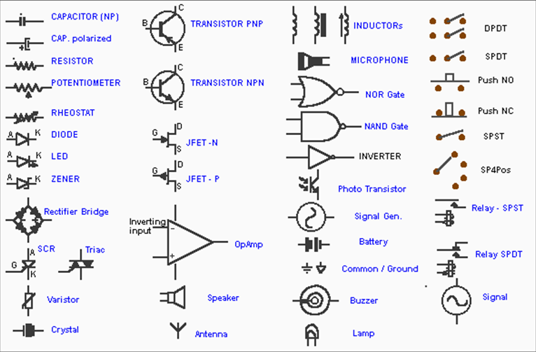
Below is the listing of most common components used in pedal building:
CAPACITORS:
A device used to store an electric charge, consisting of one or more pairs of conductors separated by an insulator.
RESISTOR:
A resistor is a passive two-terminal electrical component that implements electrical resistance as a circuit element. Resistors act to reduce current flow, and, at the same time, act to lower voltage levels within circuits.
POTENTIOMETER:
A potentiometer is a variable resistor. Turning the knob changes the resistance value across the terminals.
DIODE:
Current passing through a diode can only go in one direction, called the forward direction. Current trying to flow the reverse direction is blocked. They're like the one-way valve of electronics. If the voltage across a diode is negative, no current can flow*, and the ideal diode looks like an open circuit.
Diodes are used for different clipping textures in Overdrive and Distortion Pedals.
LED:
A light-emitting diode (LED) is a two-lead semiconductor light source. It is a pn-junction diode, which emits light when activated. LED are also used for more modern clipping textures in Distortion Pedals.
ZENER DIODE:
A Zener diode is a diode which allows current to flow in the forward direction in the same manner as an ideal diode, but also permits it to flow in the reverse direction when the voltage is above a certain value known as the breakdown voltage.
TRANSISTOR PNP and NPN:
There are two types of basic transistor out there: bi-polar junction (BJT) and metal-oxide field-effect (MOSFET). A current input into the base of the transistor allows for a much larger current across the emitter and collector leads. NPN and PNPs are exactly the same in their function, they provide amplification and/or switching capability. Used in many circuit to amplified input signals and can be use for buffer circuits .
JFET-N and JFET-P:
JFETs can have an n-type or p-type channel. In the n-type, if the voltage applied to the gate is less than that applied to the source, the current will be reduced (similarly in the p-type, if the voltage applied to the gate is greater than that applied to the source). A JFET has a large input impedance (sometimes on the order of 1010 ohms), which means that it has a negligible effect on external components or circuits connected to its gate.
OPAMP:
Short for Operational amplifier, An operational amplifier ("op-amp") is a DC-coupled high-gain electronic voltage amplifier with a differential input and, usually, a single-ended output. In this configuration, an op-amp produces an output potential (relative to circuit ground) that is typically hundreds of thousands of times larger than the potential difference between its input terminals. You will use OpAmps on many of your circuits and designs. There are so many to choose from.
BATTERY:
Used to supply voltage to your circuit. Most effect pedals use a 9 volt battery, but there are some that use larger voltages, such as 18 volts.
GROUND:
In electrical engineering, ground or earth is the reference point in an electrical circuit from which voltages are measured, a common return path for electric current, or a direct physical connection to the Earth.
Garlind Electronics, Inc. 2015 ©